A Fly-By-Wire Architecture for Multi-Threaded Windows Apps is available for Kindle and in softcover from Amazon.com and Barnes and Noble.
A Fly-By-Wire Architecture for Multi-Threaded Windows Apps
How to develop complex but reliable Windows applications quickly
By Will Warner
This book presents techniques for structuring multi-threaded Windows applications. It teaches how to use those techniques to develop complex but reliable Windows programs quickly. The only prerequisites are an understanding of object-oriented programming and some familiarity with Windows application development.
Well-behaved Windows programs that perform lengthy processing or that wait for stimulus or information from outside of the program make use of multiple threads. They must. For, otherwise, the programs will be slow to repaint their Graphical User Interface (GUI), after dragging or being uncovered, will be slow to respond to input from users, and will generally degrade the performance of the computer that is executing them. The architecture I present makes the design of a multi-threaded program easy and straightforward.
The code for a complete demonstration Windows application—FBWwinAppDemo—written in C# accompanies this book. The same could be rendered in VB.Net or any sufficiently advanced object-oriented programming language. To make the demonstration interesting, we imagine that FBWwinAppDemo controls a simple robot that can sense the infrared radiation emitted by a person and follow him around a room. To download the source code, visit www.flybywirewinapps.com.
The blue box in the center of Figure I.1 represents the FBWwinAppDemo program in context. As appropriate for a context diagram, the box is empty, for it is just one of the components of the larger system.
Figure I.1: Context diagram for the FBWwinAppDemo robot control program. Using input from a bank of infrared radiation (IR) sensors, and under the control of FBWwinAppDemo, the robot will follow an IR source (a person) around the room.

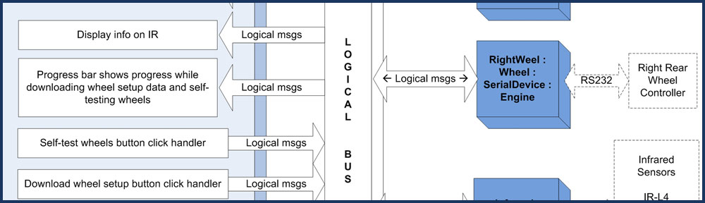
Figure I.2 depicts what will eventually fill that box. It is a diagram of the architecture of FBWwinAppDemo, the multitasking robot control program. My aim in this book is to bring readers slowly to an understanding of this architecture and prepare them to employ the concepts in their own Windows apps.
Figure I.2: FBWwinAppDemo Architecture. The program must simultaneously communicate with four wheel controllers and eight infrared radiation (IR) sensors.

These concepts come out of my thirty-five years as a computer engineer working at the nexus of software and hardware. During these years, I saw develop in the minds of R&D managers the belief that modifying software is more fraught with difficulty than messing with circuitry. What they found is that because software is asked to do so much, it is very complicated. Because it is actually so easy to change and grow its functionality, software is often created without discipline. Vast, therefore, is the effort to verify its operation and prove that modifications to it produce no unintended changes in operation.
Many in product development are more comfortable with circuit diagrams (Figure I.3), which record designs in a form that is less opaque and easier to take in. Over time I began to incorporate concepts from digital circuitry in the design of software.
Figure I.3: An integrated circuit chip (IC) in a mesh of interconnections with other components of a larger circuit. The 10-MHz clock input drives its operation. The straight lines and easy-to-trace interconnections of circuit diagrams produce a feeling of understandability for many people.

Copyright Maxim Integrated Products (http://www.maxim-ic.com). Used by permission.
Digital circuitry comprises a number of nuggets of functionality—integrated circuit chips—suspended in a mesh of interconnections, and animated by, driven by, ticks of a clock. Internally, the ICs themselves are combinations of more primitive nuggets of functionality, which in turn are made from encapsulations of even more rudimentary capabilities.
At each level, encapsulations are “black boxes” to higher levels, their overall behavior specified, but their inner make up, internal connections, and operation invisible. The IC’s external pins (Figure I.3) are its points of connection with the other components of the circuit; it is only the behavior at these connection points that is of concern to the designers of the circuit.
In addition, the ICs are interchangeable parts, so a design can employ as many copies of a part as are needed. Instances of the part behave identically. If different things come out of two of them, it is only because they received different inputs.
Early programming technique—the spaghetti code of the 1960s and even the structured programming of the 1970s—did not lend itself to picturing software in similar terms. But the emergence of object-oriented programming in the 1980s gave developers the concepts they needed to begin thinking in this way.
In object-oriented programming, a class is a nugget of functionality. Higher functioning classes derive from and extend the abilities of simpler ones or allocate and use simpler classes internally. The internal workings of the class, its private and protected methods and properties, are of interest only to the implementer of that class. Its public properties, methods, and events are analogous to the pins on the IC: they are the points of connection with the other components of the program.
Moreover, a programmer can deploy any number of instances of a given class. As with ICs, if different things come out of two instances, it is only because the two received different inputs.
Working at the junction of software and hardware also showed me the value of a fly-by-wire architecture. Fly-by-wire systems employ a local-area-network (LAN) as a backbone upon which to hang the major components of the system. The physical connection among them is only the wires of the LAN. The modules of functionality communicate by way of messages over the LAN.
I assume the term “fly-by-wire” comes from airplane design, which at some point replaced direct connection by cables between the ailerons on the wings and the pilot’s stick, say, with a LAN that conveyed messages from embedded computers sensing movements of the stick to computers embedded with motors on the ailerons. Those messages describe what the aileron-controlling motors should do based on what the pilot does with the stick.
Automobiles today are fly-by-wire systems. The sensors (e.g., window up/down buttons) and actuators (e.g., window up/down motors) do not connect directly. They, along with all other devices in the car (including the radio) are modules on a LAN that snakes throughout the vehicle; they communicate using messages over the LAN.
When a passenger presses the right-front-window-down button, that button sends a “right-front-window-down-button-pressed” message. The right-front-window up/down motor sees that message, and down goes the window. When the passenger lets up on the same button, the button sends a “right-front-window-down-button-no-longer-pressed” message. The right-front-window-up/down motor sees that message and stops lowering the window. Almost everything in the car works like this.
This way of operating gives a designer a lot of power to implement complicated features. For example, the car might contain a built-in telephone that sends a “phone’s-ringing” message when the telephone begins ringing. The window-control motors on all windows could see that message and automatically roll up all the windows. The radio could see the message and turn down its volume. I’m not saying you would want the car to behave this way, only that it would be easy to do using the fly-by-wire methods.
My idea is to use the fly-by-wire concepts in complex Windows applications. I don’t mean as part of a system in which the Windows app is one of the components, but rather within the Windows program itself. In such a program, the nuggets of functionality are classes that do most of their processing in child threads. These components of the program communicate using messages sent on the software equivalent of the LAN in fly-by-wire systems, that is, on a “logical bus” within the program itself. (Figure I.2.)
Using a logical bus over which the components of the program communicate makes possible a very powerful debugging and testing aid. The program may include a special component with its own GUI, whose job is to display and/or log messages that appear on the bus. This is analogous to “sniffers,” devices that record and display communication between two devices over an RS232 connection, say. Being able to see who said what to whom, and when, is very helpful in debugging.
As developers, you can equip the debugging component’s GUI with the ability to interact with you and interject messages, messages that will, eventually, come from a program element that is not yet implemented. This helps you test the program as you breathe life into it.
These techniques also assist with unit testing. If individual modules within the program function by responding to messages, unit-test code can stimulate the modules with those same messages and assess the response.
Another advantage to this approach is that the highest-level diagram of every fly-by-wire Windows app looks like Figure I.2. It is a collection of boxes representing nuggets of functionality, interconnected by the logical bus. Add as many boxes as you need, give them names that suggest their roles in the program, define the messages they send and the data the messages carry, and you’ve got your high-level design.
As seen in the diagram, this architecture makes use of another technique from digital circuitry, the clock. Ticks of the (software) clock drive processing and, especially, synchronize activity and communication among the various threads.
These programs rely very heavily on events to carry forward processing. This makes possible a style of coding I call “unconditional programming” because very little of the code will contain branches. Years ago we condemned the “goto” statement, and I now question the use of if-statements for the same reason: they add complexity to code, making it harder to understand and modify. I devote parts of this book to promoting a style of programming that minimizes the use of the if-statement.
Finally, I will make some potentially controversial observations about software development methodologies and incorporate my views on what constitutes elegance in software design.
The FBWwinAppDemo program presented here comprises two projects. One—WinAppInfrastructure—produces a dynamic-linked-library that furnishes the fly-by-wire infrastructure. The other project—RobotController—includes the forms and additional classes that make use of the infrastructure to achieve the functionality required of the robot controller. Thus segregated, the FBW infrastructure is available to underlie any Windows application.
Table of Contents
Introduction
Notational Conventions
Chapter 1: Building Blocks
1.1 Multi-Threading and the GUI-Event Thread
1.2 Object Queues and Protected Objects
1.3 Signals
1.4 The Clock and Clocked Objects
1.5 Clocked Signal
1.6 Clocked Object Queue
1.7 Blocking Object and Interruptible Delay
1.8 Blocking Object Queue
Chapter 2: Flying By Wire
2.1 Logical Bus and Bus Nodes
2.2 Logical Messages
2.3 Child Threads
2.4 Message Queues
2.5 Message Processing Threads
2.6 Engines and Jobs
2.7 FBW Initialization and Program Shutdown
Chapter 3: FBW Aids
3.1 Dual-Use Buttons
3.2 One-Shot Timers.
3.3 Progress Bar Manager
3.4 Timer
3.5 Registered Message Handlers
Chapter 4: FBWwinAppDemo – Design Principles
4.1 Design Goals
4.2 Unconditional Programming
4.3 Need to Know
4.4 State Machines
4.5 Elegance in Program Design
Chapter 5: FBWwinAppDemo – Design
5.1 What Can You Do for Me
5.2 Constructing FBWwinAppDemo
5.3 FBWwinAppDemo States
5.4 Jobs
5.5 Bus Nodes
5.6 Logical Messages
5.7 Controls on the Main Form
5.8 Wheel Monitor Controls
5.9 Progress Bar Control
5.10 Show IR Control
5.11 Debug Forms
Chapter 6: Heretical Thoughts on Software Development Process
6.1 Discovering Your Design
6.2 Coding Standards
6.3 Testing
6.4 Define “Done”
6.5 Killing Trees
6.6 The Dark Side of Process
Appendix: Coding Standards.